

Designing for ARIA
A practical design guide for partners
This guide covers the key design principles for printing with ARIA. The recommendations are proven starting points rather than hard limits. If your design pushes beyond them, get in touch—we're always happy to advise.
Introduction
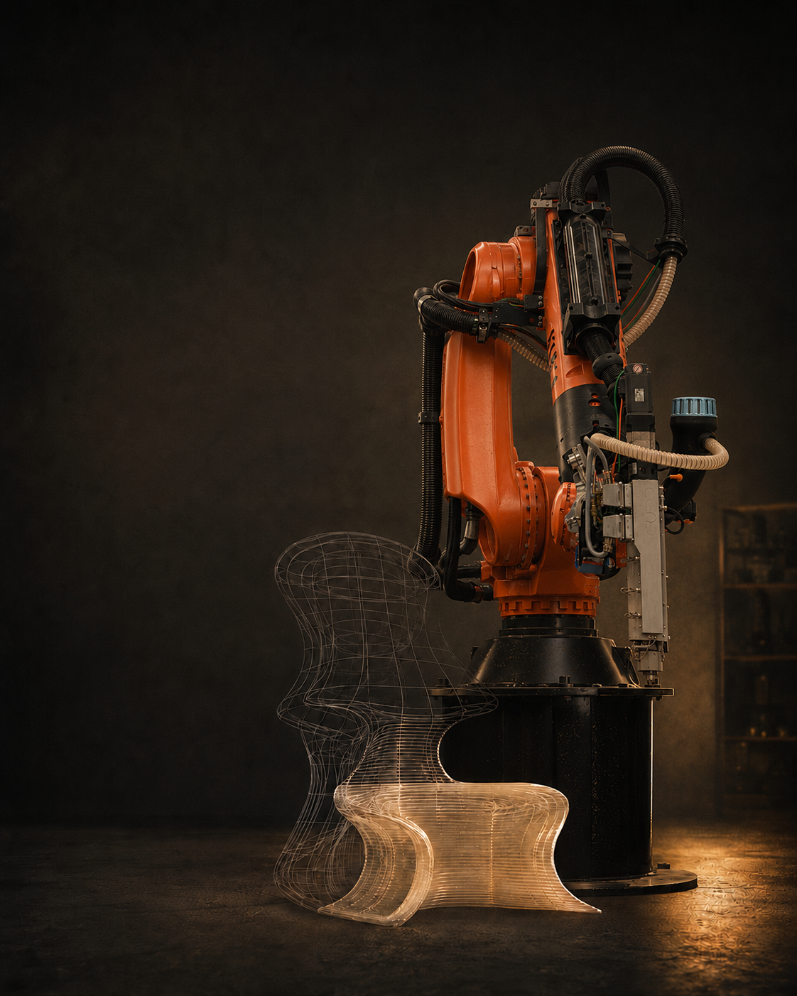
ARIA is a tool. Admittedly, a very large, bright orange one. She is a six-axis KUKA robot fitted with a CEAD E25 pellet extruder, building objects one continuous bead of thermoplastic at a time.
She gives us a way to turn ambitious digital forms into real objects at a scale conventional FDM cannot touch. But she is not magic. Bead size, heat, layer time, gravity and the route the robot needs to take all shape the finished piece.
The Short Version
Think in continuous curves, generous radii and self-supporting forms. Let the layers become part of the design. Interesting shape? Awkward scale? Good. Bring us in early
The Starting Point
1.5m x 1.5m x 2m
Recommended Design Envelope (1)
Default Materials
Typical construction
Printed material
Preferred file format
Final Manufacture
ca. 500mm
Recommended minimum path length per layer (2)
2.5 to 34.5mm
Single-pass bead width range (3)
This guide primarily assumes recycled transparent PETG. Material-specific guidance may differ when printing in bio-based PLA.
Hollow, continuous-wall forms are often the cleanest starting point. Ribs or double walls may be added where the design needs them.
Assume one material per build unless we agree otherwise.
STEP solid geometry, supplied at full size in millimetres.
Subject to toolpath, structural, thermal, lighting and safety review.
The actual maximum print envelope is 2 m × 2 m × 3 m, although the available design freedom becomes more limited as a piece approaches these dimensions.
Shorter path lengths are possible, but thermal considerations become increasingly important. They generally require smaller nozzles and slower print speeds, increasing production time and cost. The minimum viable path length also increases with nozzle size.
Printable bead size depends on the nozzle diameter and layer height. Refer to the ‘Nozzles, beads and corner radii’ section for the recommended bead dimensions.
Six principles that make life easier
ARIA offers considerable design freedom, but the best results come from working with the process rather than against it.
These six principles provide a useful starting point, helping designs move more smoothly from CAD to print while making the most of the scale, material and character of robotic additive manufacturing.
They are not hard limits, and there is always room for experimentation, but ignoring too many of them at once is likely to make ARIA unhappy.
1. Give ARIA a clean route
Closed loops and long, flowing contours tend to give the cleanest result. Every start, stop and travel move can leave a seam or a change in the surface.
2. Curves are your friend
Sharp turns make the robot slow down while it is still managing a substantial flow of material. A generous radius helps the movement, the bead and the finish.
3. Let the form support itself
As a starting point, keep walls within about 45 degrees of vertical. Angles up to around 60 degrees may be possible but become increasingly difficult to print. Avoid bridges, flat ceilings and forms that rely on removable support material. It can be done, but it is certainly not ARIA’s strong point.
4. Work with the bead
Walls, ribs, gaps and details need to relate to the chosen bead width. Features that sit awkwardly between viable bead multiples may be rounded, thickened or lost in the toolpath.
5. Give each layer time to settle
Very short paths can stay too hot and soften beneath the next layer. Sudden reductions in circumference, narrow necks and isolated towers deserve an early conversation.
6. Let the process show
Printed recycled transparent PETG should be thought of as translucent rather than perfectly optically clear. Layers, toolpath changes, natural material variation and the interaction between gravity and molten plastic all influence how it catches and diffuses light. Embrace these characteristics and make them part of the design.
Nozzles, beads and corner radii
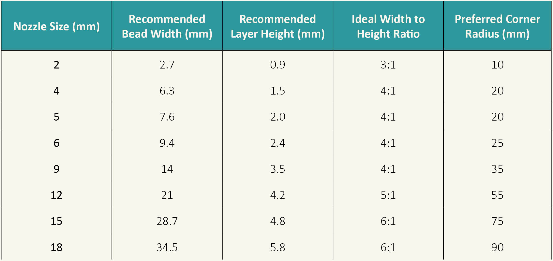
A larger nozzle does not simply make the same object faster. It changes the scale of the bead, the layer and the details that will survive the journey from CAD to print. The CEAD values below are reference starting points; we confirm the production settings for each form, material batch and intended finish.
How to use the table
Choose the nozzle for the scale and finish of the whole object, not for one isolated detail.
Treat a single printed wall as approximately one nominal bead wide.
Design thicker walls and ribs as intentional multiples of bead width.
As a general guide, avoid standalone details, slots and gaps below 10 mm. Larger nozzles need proportionally larger features, and every small detail remains subject to toolpath review.
Printing outside the recommended values for each nozzle may be possible but should be discussed with The Lumi Studio team first.
The cornering rule of thumb
For early design work, allow a plan-view radius of at least 2.5 x nominal bead width, rounded upwards. This is a conservative Lumi Studio house rule, not a universal LFAM standard. A tighter turn may be possible, but it needs review and may call for a smaller nozzle, a different toolpath or an accepted change in finish.
What tends to work - and what needs a conversation
Overhangs, bridges and openings
As a starting point, keep walls within about 45 degrees of vertical. Angles in the region of 55–60 degrees may be possible, but require careful consideration of the geometry, bead size and layer height. Finish-critical forms generally require a gentler angle.
Use tapers, arches or teardrop-shaped openings in place of unsupported horizontal undersides.
Avoid large bridges and flat enclosed roofs. Split the part, leave it open or introduce a supported transition.
We avoid support material at this scale. Design the form to print without it wherever possible.
Heat and changing sections
Focus on gradual changes in diameter, perimeter and wall angle.
Avoid sudden transitions from a large body to a small loop; the smaller section may receive the next hot layer before it has stabilised.
Avoid isolated towers or fins that create repeated short paths.
Very long layers may cool too far before the next layer arrives, which is particularly problematic in areas with large overhangs. The Lumi Studio will assess this during toolpath planning.
Bases, joints and fixings
Long straight bases and large flat footprints are more prone to movement as PETG cools and contracts. We may adjust the contact geometry or add a temporary build feature.
Do not rely on an as-printed surface for close-tolerance mating, sealing or alignment.
Where fixings are required, the addition of solid local pads is advised for holes, inserts or components fitted after printing.
Printed threads are generally not viable at this scale, except where they are very large and strength is not critical.
Use mechanical connections that allow the luminaire to be assembled, serviced and separated at end of life.
Identify any load paths, suspension points and centre-of-gravity concerns in the submitted design so The Lumi Studio can prepare the part with these in mind. Responsibility for any formal engineering calculations remains with the designer.
Surface Finish
Layer lines are a defining feature of the process and will remain visible. Additional processing is possible but is extremely time-consuming and costly to undertake.
Corners, seams and changes in speed can create local variations in final geometry, gloss and transparency.
What shows as clear in CAD will rarely be perfectly optically clear when printed. Always assess light quality using a representative material sample
Identify any visually critical surfaces or preferred seam positions so we can take them into account when preparing the print.
Circular by design
Using recycled material does not automatically make a product circular. The whole luminaire should be designed as an assembly that can be safely used, maintained, repaired and eventually separated. The following principles help keep material use sensible and give each component the best chance of a useful next life.
Thermal separation
Keep LEDs, drivers and other heat-producing components appropriately separated from the printed PETG body.
Service access
Provide access for wiring, connectors, maintenance and replacement of light sources and control gear.
Mechanical fixings
Use removable mechanical fixings in preference to permanent adhesives wherever practical.
Material separation
Do not trap metalwork, electronics or dissimilar materials inside an inseparable printed shell.
Compliance
Final electrical, thermal, photometric and structural compliance remains part of the product-development process.
Material efficiency
Use the least material that meets the functional and structural requirement.
Disassembly
Make different materials easy to identify, separate, repair and replace.
Recoverability
Avoid decorative additions that prevent the PETG body from being recovered or recycled.
Material record
Record material, components and assembly method for future maintenance and end-of-life decisions.
What to send us
The more we understand about the design and how it is intended to work, the better we can prepare it for printing. Not every detail needs to be finalised at this stage, but the following information will help us assess feasibility, select the right process and avoid unwelcome surprises later.
3D Geometry
Ideally a clean STEP file at full size and modelled in millimetres. STL and other formats may be acceptable dependent on geometry and size.
Visual Intent
Renders showing the intended orientation, light effect and critical surfaces are very useful references as your files are processed.
Lighting Intent
Proposed light source, driver and optics, including the intended light effect, thermal management and access requirements.
Assembly Requirements
Details of mounting, suspension, joints, inserts, cable routes and replaceable components.
Performance
Details of any loads, required tolerances, fire or impact requirements and the intended operating environment.
Every design is reviewed by The Lumi Studio before manufacture. We may recommend changes to the geometry, scale, nozzle, orientation, assembly or toolpath before approving it for production.